Thus, the presented rectenna demonstrates the remarkable combination of compactness, flexibility and stability. It is demonstrated that for different bent states, the proposed flexible harvester does not display large variations in harvested power. The system is characterized in multiple bent configurations featuring high and stable performance. The rectifier exhibits an almost flat efficiency over the 2.3-2.5 GHz frequency span despite a wide load variations. The rectifier along with a miniaturized monopole antenna are then tailored for a flexible substrate with a resulting efficiency around 50% at 0 dBm input power. Its performance is compared with a reference rectifier that relies on a typical open circuit shunt-stub matching network.

This topology is demonstrated on a 2.4 GHz rigid harvesting system with a resulting power conversion efficiency that reaches up to 58% over 0 dBm input RF power.

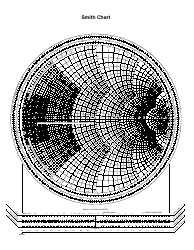
The system relies on a dual-tapered transmission line-based matching network that stretches the rectification capability of an integrated Schottky diode. This paper presents a new compact lightweight radio frequency (RF) energy harvesting system. The proposed solution can therefore be implemented in situations where it is critical to minimize the power consumption of sensors that rely on RF harvesting as their source of power. Moreover, the address detector is characterized by a current consumption of 160~nA in idle mode. The designed system relies on passive components to boost the received signal to 4.5~V at the output. In fact, charging can be initiated from input power levels as low as -18.2~dBm and a sensor can be triggered starting at power levels that are as low as -40 dBm. The proposed system exhibits high sensitivity to low power levels. Additionally, the UAV modulates the transmitted signal to encode an address that triggers a particular sensor from sleep mode to active mode. The signal transmitted by the UAV is harvested and rectified to DC voltage to power a sensor on the ground. In this paper, we design and implement a radio frequency (RF) energy harvesting and wake-up system that scavenges a 2.4 GHz signal from an unmanned aerial vehicle (UAV). The resulting impedance is now normalized to 50 Ω which results in the point Zfinal =1.04-j0.08 Ω as indicated on the smith inside the VSWR=2 circle and very close to 50 Ω system impedance. De-normalizing this point to 20 Ω leads to the input impedance of the circuit being equal to (52 -j4) Ω. Such distance is equivalent to the length of the "feed line". This point is then moved by a distance of 0.0986λ to reach the point (Zin'). This corresponds to the point (ZI') on the smith chart in Fig. The transformation from 100 Ω to 20 Ω is done by first de-normalizing ZI to 100 Ω and then normalizing it back to 20 Ω. At this stage, the impedance faces the "feed TL" that has a characteristic impedance of 20 Ω. The λ/4 load transmission line transposes the diode impedance from (Zout) to (ZI) as shown in Fig. The diode is located on the line with 100 Ω characteristic impedance, therefore its impedance is first normalized to 100 Ω and placed on the smith chart as (Zout). The change in the impedance at various points along the proposed matching network is demonstrated in Fig. By tuning the lengths and characteristic impedances of both transmission lines sections, (Zin) of the entire network is optimized to be 50 Ω. A capacitor (C) prevents the DC voltage generated by the diode from reaching the generator.
Printable smith chart series#
The second transmission line in series is the "feed TL" that is characterized by an impedance (Z0F), a length (LF) and a width (WF).

The function of this line is to transform the diode impedance (Zout) into (ZI). 1, the transmission line, characterized by an impedance (Z0L), a length (LL) and a width (WL), constitutes the "load transmission line (TL)". The topology of the proposed matching network is shown in Fig. In this work, (Zout) is chosen at 2.45 GHz and for an input power level of -10dBm. The Schottky diode's impedance (Zout) varies with both frequency and input power. In this section, the proposed matching network aims to match the load composed of the SMS7630 zero-bias diode to the 50 Ω source. of the main challenges in designing an efficient rectifier is the incorporation of an appropriate matching network that can achieve the match between the Schottky diode and the source.


 0 kommentar(er)
